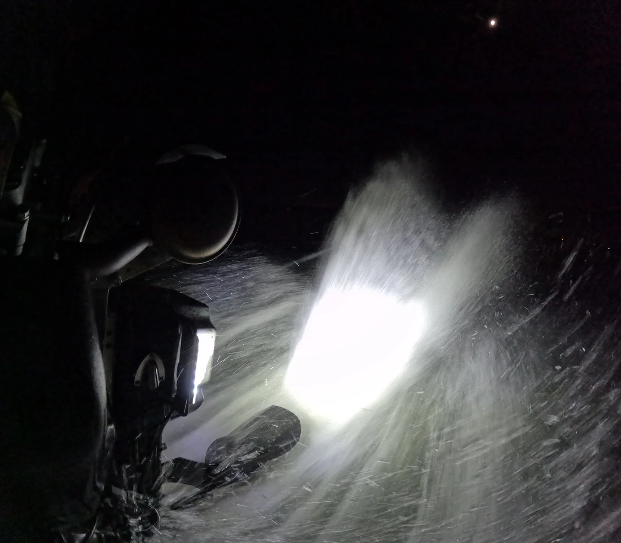


Includes TWO rooster tails mounted on a bracket for EITHER side of your Mud Buddy motor!
WIRING MATERIALS NOT INCLUDED
Please note in the order comments what color Rooster tails
1. Tools and Materials
Tools
• Metric socket set with 10 mm socket (engine plastics)
• Standard socket set with 5/16 hex driver (belt housing case bolts)
• Torque wrench (to manufacturer spec for case bolts)
• Wire snips, strippers, fish tape / pull string
2. Bracket Installation
Both brackets mount to the existing belt-housing case bolts (5/16 hex). Bracket holes accept the case bolts cleanly but snugly.
2.1 Orientation
Each bracket has an irregular (notched) side and a beveled side. The bracket can physically install in either orientation, but only one provides adequate top-case clearance.
1. Dry-fit each bracket against the belt-housing case with the beveled edge oriented up.
2. Confirm clearance between the top of the bracket and the case. This orientation gives the most clearance and the least binding.
3. Do NOT install with the irregular (notched) side up — this orientation leaves almost zero clearance at the top of the case and feels tight when torqued.
2.2 Hardware Stack-Up and Torque
1. Remove existing belt-housing case bolts one side at a time so the case stays seated.
2. Stack the hardware in this order from the case outward: case → lock washer → bracket → bolt head. The lock washer between the case and the bracket gives the maximum bracket-to-case spacing.
3. Hand-thread each 5/16 hex bolt through the bracket and into the case. Do not cross- thread; the bracket hole tolerance is snug and any side-load on starting threads can gum the case threads.4. Torque to factory case-bolt spec.
Risk: If bracket-hole tolerance trends any smaller in production, there is a real risk of stripping case threads. Flag any bolt that does not start cleanly by hand.
2.3 Wire Retention Clip
Each bracket includes a wire retention clip for the light-side harness.
1. On the left (port) bracket, mount the retention clip per as-shipped placement.
2. On the right (starboard) bracket, mount the retention clip on the bottom side of the
bracket rather than the top. Top-side placement is workable but exposes more wire;
bottom-side gives a cleaner tuck and better protection.
3. Harness Routing
The harness runs from the starboard light, across the engine block, down the port side past the
engine plastics, into the transom raceway, and forward to the battery compartment / OEM switch
panel.
3.1 Cross-Block Routing (Starboard to Port)
1. Identify the gap between the belt-housing case and the engine block where the throttle cable runs. This gap is the clean routing path from the starboard light to the port side.
2. Feed the starboard light harness through this gap, keeping it parallel to the throttle cable and away from any moving belt or pulley surfaces.
Heat note: Routing next to the throttle cable in this gap does not present an overheat / melt risk for the lights or wiring based on initial testing.
3.2 Port-Side Plastics Access
1. Remove the left-side (port) engine plastics by removing the 10 mm bolts.
2. With the plastics off, locate the wire path along the bottom of the engine block that leads toward the bell housing. There is a visible gap viable for routing.
3. Run the harness through this gap toward the raceway entry point.
3.3 Transom Raceway to Battery Compartment
1. Locate the existing transom raceway that carries the fuel line and other wire bundles from the engine bay forward into the hull.
2. Feed the light harness through the same raceway alongside the existing bundles. Expect a snug — but not tight — fit.
3. Pull harness forward until it reaches the battery compartment with adequate slack for internal battery box work.
Havoc MSTC note: On older (prefoam) Havoc MSTC configurations, the as-shipped 8-foot
overall length reaches the OEM switch panel without an extension. There is approximately
56 inches of slack measured from the transom on the short side, which is adequate for
internal battery-box work.
3.4 Reassembly of Engine Plastics
1. Before reinstalling the port-side plastics, confirm the harness does not cross or rest against the 10 mm bolt hole used for the engine cover.
2. Route the harness clear of the bolt hole and secure with an adhesive clamp, zip-tie, or P- clip if needed.
3. Reinstall the plastics with the 10 mm bolts. Verify no chafe or pinch on the harness after seating.
Risk: This is the single most common chafe / pinch point in the install. Improper reassembly
of the plastic shroud will pinch or chafe the wire at the 10 mm bolt boss.
4. Power Termination and Switch Panel
1. Land the power lead in the battery compartment at the intended switched circuit.
2. Verify polarity before final connection.